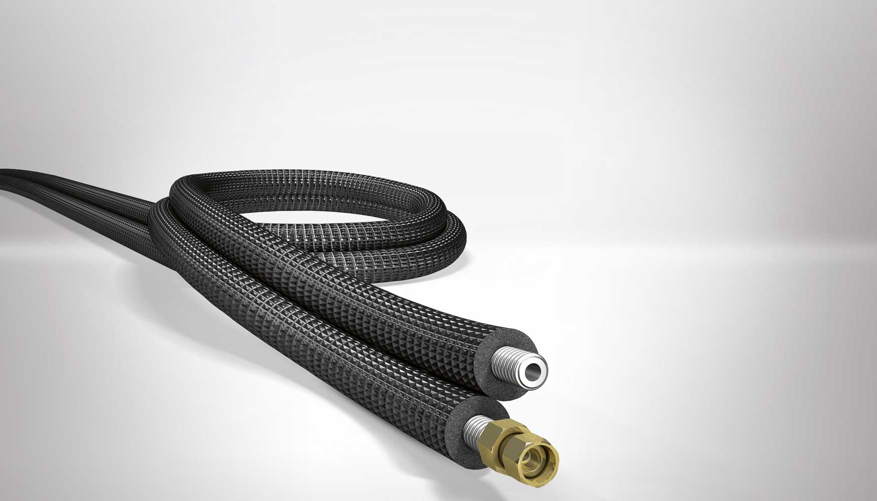
Connection of different components of the solar system is carried out with pipes, until the necessary hydraulic circuits are formed.
Normally, materials used for primary circuit pipes are copper, black steel and plastic materials
The cross-linked polyethylene pipes can be used without problems, provided that manufacturer guarantees their use above 120º C.
Galvanized steel should not be used in primary circuits (from collectors to storage) due to the strong deterioration that zinc protection undergoes with temperatures above 65º C.
In general, the fluid velocity must not exceed 1.5 or 2 m / s in the primary circuit.
Pipes diameter can be selected so that fluid flow velocity is less than 2 m / s when pipe runs through inhabited places and at 3 m / s when the route is outside or by uninhabited places.
When steel is used in pipes or fittings, working fluid pH should be between 5 and 9.
Pipes dimensioning will be carried out in such a way that the load unit loss in pipes never exceeds 40 mm of water column per linear meter.
The circuit load total loss must not exceed 7 m of water column.
The maximum load loss is applicable to primary circuit and secondary circuit. If it were larger, we would be obliged to choose the immediately superior pipe diameter.
For pools heating, PVC pipes are used, which can have large diameters without a significant additional cost.
All piping networks must be designed in such a way that they can be emptied partially and totally, through an element that has a minimum nominal diameter of 20 mm.

For pipeline selection, following aspects must be taken into account:
1º Fluid compatibility:
Materials to be used for ACS circuits may be:
• Metallic:
– Galvanized steel, UNE-EN 10.255 M series (only in cold water).
– Stainless steel, UNE-EN 10.312, series 1 and 2.
– Copper, UNE-EN 1.057.
• Thermoplastics:
– Non-plasticized polyvinyl chloride (PVC), UNE-EN 1.452.
– Chlorinated polyvinyl chloride (PVC-C), UNEEN ISO 15,877.
– Polyethylene (PE), UNE-EN 12.201.
– Crosslinked polyethylene (PE-X), UNE-EN ISO 15.875.
– Polybutylene (PB), UNE-EN ISO 15.876.
– Polypropylene (PP) UNE-EN ISO 15.874.
– Multilayer polymer / aluminum / polyethylene (PE-RT), UNE 53.960 EX.
– Multilayer polymer / aluminum / polyethylene (PE-X), UNE 53.961 EX.
Aluminum tubes and those whose composition contains lead are expressly prohibited.
2º Work pressure:
A minimum pressure of 1 bar and a maximum of 5 bar must be guaranteed at all points of consumption; so you can take 5 bars as pressure for series selection.
Although tanks safety valves are usually set at 8 bar this is a more appropriate design pressure.
3º Working temperature:
Hot water and heating pipes should remain stable with system working temperatures, sporadically be able to reach temperatures close to 95 ° C and continue to resist with a life expectancy of at least 50 years.
4º Charge loss:
When a liquid circulates inside a straight tube, its pressure decreases linearly along its length, even though it is horizontal.
That pressure drop is called charge loss.
Valves, constrictions, elbows, direction changes, derivations, etc. they cause load local or singular losses that must also be taken into account.
Total load loss, which is the sum of linear load loss and singular load losses, must be determined.

5º Pipe size:
To calculate pipe size we start from the flow data.
We must determine pipeline minimum diameter (ie the most economical) without load loss exceeding a reasonable limit, so as not to be forced to use a higher power pumping group with the consequent energy waste.
We know from experience that fluid circulation speed maximum recommended is approximately 1.5 m / s if it does so continuously (primary circuits) and 2.5 m / s if it does so at intervals (secondary consumption circuits).
It is also recommended (or required) that pressure drop for each tube linear meter does not exceed 40 mm ca.
These 2 conditions impose a lower limit on pipe diameter.
It is usual to start from an estimated diameter based on experience in similar systems and verify that choice implies values of load loss and speed lower than recommended maximums.
If this is not the case, verification should be repeated for an immediately larger diameter.
If on contrary, we can select a smaller diameter than initial one, we will save on material; especially if circuit has a considerable length.
As a first approximation, we can resort to following formula:
D = j C 0.35
Being:
D diameter in cm
C flow in m3 / h
j 2,2 for metal pipes and 2,4 for plastic pipes.
Initial estimation, whatever method used, must be verified by using load loss tables or abacuses.
There are tables and specific abacuses for each type of material (copper, steel, plastics) that allow to determine load loss due to friction and fluid speed in the tubes.
This content was extracted from the Solar Thermal Energy Technical-Commercial Manual and is part of Solar e-learning.
All you need is Sun. All you need is Sopelia.
