Tag Archives: energias renovables

Mexico Solar PV

Mexico is part of the solar belt, an area that considers countries with the highest solar radiation in the world.

The country set itself the goal of generating, by 2024, 35% of electricity with clean energy (currently 80% is generated with hydrocarbons).

It is estimated that solar energy will represent 13% of all energy for next year, and that their participation will gradually grow.

However, solar technology development, as in all Latin American countries (and almost entire world), presents a huge imbalance between large-scale projects and distributed generation.

As far as large-scale projects are concerned, with 37 solar power plants under construction and an estimated investment of US$ 5,000 million, Mexico aims to become a solar power thanks to regulatory support and enviable geographic conditions.

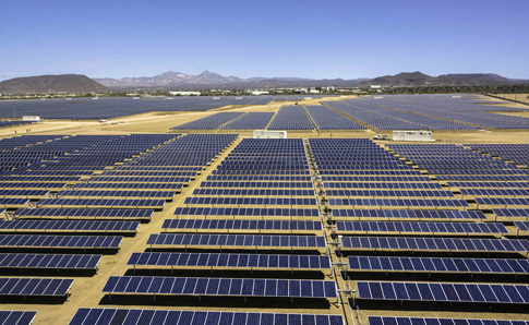
In Coahuila is the largest solar park in Latin America with an investment of US$ 650 million generates about 754 MW.
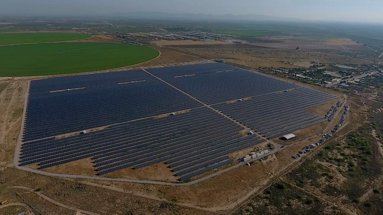
By the end of 2020, the country will have 5,000 MW of installed capacity.

This impulse is due to the Energy Reform that opened the sector to private initiative, the Energy Transition Law and the three electric auctions held to date.

Average price obtained in the third solar auction (in which contracts were assigned to 9 projects) represented a downward world record for all energies.

In sector, presence of foreign actors stands out, winning approximately 90% of the bids.

The other side of the coin is that of distributed generation.

Ver las imágenes de origen

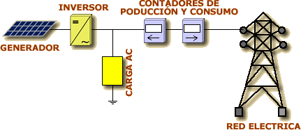
Although since 2007 it is possible to install solar panels in homes, shops and industries and connect them to the electricity grid; until 2017, necessary conditions distributed generation development were not created. It represents less than 0.3% of total electricity generation in Mexico.

Before Energy Reform, distributed generation could only be used for self-consumption (and surpluses were lost after 12 months), without it being possible to buy or sell photovoltaic solar energy.

Regulations approved in March 2017 regulate the following compensation models: 1) Net metering; 2) Net billing; 3) Total sale.

In addition, due to ignorance advantages of using solar energy, which could supply a home with high electricity consumption, with only 16 square meters of photovoltaic panels, are lost in Mexico.

Most people are unaware that installing a renewable technology system based on solar panels in their homes is legal, simple and accessible,

Another challenge to face trained personnel lack both technically, to install panels, and engineering, for systems design.

Betting only on large-scale projects is an absurd and non-logical proposal that makes renewables a financial product and not an energy policy tool that promotes employment and technological and industrial development at national level.

It favors macro projects and deepens energy sector convcentration.

Low prices concentration in auctions, with the consequent creation of a dominant position in a few actors (usually foreign companies), will in long term dilute the advantages of low short-term prices.

If we consider auctions as the only tool to increase renewables participation, we will be maintaining an obsolete energy matrix paradigm and committing a very serious error.

The future energy matrix is based on 3 pillars:

1) Energy efficiency

2) Renewable energies

3) Distributed generation

The path of energy revolution and citizen empowerment goes through prosumer figure development and energy cooperativism.

The way of concentration and centralization involves only changing fossils for renewables to maintain the “status quo” for benefit of those who always will continue to act as a collection agency in collusion with political party in government.

All you need is Sun. All you need is Sopelia.

Solar Wiring

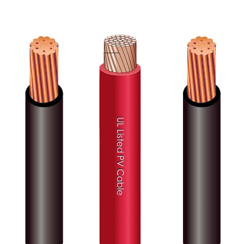
Cables, both direct current (DC) and alternating current (AC), if correctly sized, will minimize energy losses and protect the installation.

For a photovoltaic system, DC cables must meet some requirements:

* Have grounding line and protection against short circuit.
* Be resistant to UV rays and adverse weather conditions with a wide range of temperatures (approximately between -40ºC and 110ºC).
* Possess a wide voltage range (more than 2000 V).
* Be simple and easy to manipulate.
* Be non-flammable, of low toxic level in case of fire and without halogens.
* Have a very low conduction loss (up to 1%).

Photovoltaic installation cables must have certain characteristics that differentiate them from conventional cables, although many argue that differences are not very large.

Since voltage in a photovoltaic system is low DC voltage, 12 or 24 V, currents that will flow through the cables are much higher than those in systems with 110 or 220 V AC voltage.

Power amount in Watts produced by the battery or photovoltaic panel is given by the following formula: P = V. I

V = voltage in Volts
I = current in Amperes

This means that to supply a power at 12 V current will be almost 20 times higher than in a 220 V system. It implies that much thicker cables must be attached to prevent overheating or even a fire.

Following table indicates recommended cable section according to power and for different voltage levels.

For very low voltages and low power demands, very thick cables must be used. For example, to reach a power of approximately 1 Kw at 12 V we would need a 25 mm2 section cable. The same as to supply 20 Kw at 220 V.

This increases system price drastically because thicker cables are more expensive.

That is why it is very important that the lengths of DC wiring are as short as possible.

When designing large systems, a cost / performance analysis must be performed to choose most suitable operating voltage. It would be advisable to gather small groups of modules and if possible to make operating voltage higher than 12 or 24 V.

To verify cable section values recommended in tables, maximum voltage drops compared to voltage at which you are working should be below the 3% / 5% limit.

To calculate the relationship between conductor section and its length we can apply following formula:

S = 2 r. l. i / ΔV

Being:

r Conductive material resistivity (0.018 in case of copper conductors)
l Cable section length
i Current intensity
ΔV Voltmeter reading difference

Let’s see an example:

Battery terminals output voltage is 13.1 V. The main line between it and a device, which consumes 60 W, measures 12 m of 6 mm2 cable.

We must find the voltage value at device input to verify that we are within maximum recommended values of voltage drop.

The intensity i = P / V = 60 / 13.1 = 4.6 A

S = 6 = 2. 0.018. 12 4.6 / ΔV

ΔV = 0.33 V

Therefore, voltage at device input will be: 13.1 – 0.33 = 12.8 V

Voltage drop is 2.34% (maximum recommended value: 3%).

It is normal to use tables to select recommended section and use the formula to calculate the voltage drop and perform the verification.

In case that voltage recommended maximum values drop are exceeded, we will select section immediately above and we will carry out verification again.

Cables for photovoltaic applications have a designation, according to regulations, which is composed of a set of letters and numbers, each with a meaning.

Cables designation refers to a series of characteristics (construction materials, nominal voltages, etc.) that facilitate the selection of the most suitable to the need or application.

This is an extract of contents included in Technical-Commercial Photovoltaic Solar Energy Manual and Sopelia e-learning training.

All you need is Sun. All you need is Sopelia.

Heat Transfer Fluid

Heat transfer fluid passes through absorber and transfers energy to thermal utilization system (accumulator or exchanger).

Most used types are:

* Natural water: can be used in open circuit, when sanitary water passes directly through collectors, or in closed circuit (independent consumption circuit).

In first case, circuit can only be constituted by materials allowed for drinking water supply. In some countries this system is not allowed.

It will be necessary to consider water characteristics, especially its hardness (calcium and magnesium amount), which when heated produces a hard crust or tartar.

This crust accelerates corrosion, restricts flow and reduces heat transfer. The values start to be problematic from 60 mg / l. Very soft waters can also cause problems due to their corrosivity.

* Water with antifreeze: to avoid drawbacks of freezing and boiling of heat transfer fluid, use of antifreezes called “glycols” is the most widespread.

Mixed with water in certain proportions prevent freezing to a limit of temperatures below 0 ° C depending on their concentration.

On the other hand the boiling point rises making heat transfer is protected against too high temperatures.

Choice of concentration will depend on historical temperatures of the area where installation is located and on characteristics provided by manufacturer.

Most commonly used glycols are ethylene glycol and propylene glicol.

Resultado de imagen de tabla anticongelante solar

Fundamental characteristics of antifreeze:

• They are toxic: their mixing with drinking water must be prevented by making secondary circuit pressure greater than that of primary, for prevention exchanger possible breakage.

• They are very viscous: factor to take into account when choosing electric pump that is usually more powerful.

• Dilates more than water when heated: as a safety standard, when we use antifreeze in proportions of up to 30%, when sizing the expansion vessel, we will apply a coefficient of 1.1 and 1.2 if proportion is greater.

• It is unstable at more than 120ºC: it loses its properties so it stops avoiding freezing. There are some that withstand higher temperatures, but they are expensive.

• The boiling temperature is higher than that of water alone, but not too much.

• Specific heat is lower than that of water alone, so it must be taken into account in the flow calculation, conditioning pipe and pump dimensioning.

To calculate antifreeze amount that must be added to an installation, you must first consult the table of historical temperatures which is the minimum temperature recorded in that city or location.

Once it is known, goes to glycols graph supplied by manufacturer and value is transferred to indicate what percentage is.

* Organics fluids: there are two types, synthetic and petroleum derivatives.
Precautions mentioned in case of antifreeze regarding toxicity, viscosity and dilation are applicable to organic fluids. Additional risk of fire should be mentioned, but also that they are chemically stable at elevated temperatures.

* Silicone oils: they are stable and of good quality products. They have the advantages that they are not toxic and that they are not flammable, but current high prices mean they are not widely used.

All you need is Sun. All you need is Sopelia.

The Solar Converter

They are equipment capable of altering voltage and characteristics of electric current they receive to transform it into suitable for specific uses.

Those that receive direct current and transform it into direct current with a different voltage are called DC-DC converters. They are not widely used in photovoltaic systems.

Those that receive direct current and transform it into alternating current are called DC-AC converters or inverters. The function of an inverter is to change a DC input voltage to a symmetrical AC output voltage, with the magnitude and frequency desired by user.

They allow to transform 12V or 24V direct current that modules produce and store batteries, in 125V or 220V alternating current.

This allows use of electrical devices designed to work with AC.

A simple inverter consists of an oscillator that controls a transistor, which is used to interrupt incoming current and generate a square wave. This square wave feeds a transformer that softens its shape, making it look like a more sinusoidal wave and producing the necessary output voltaje.

Ver las imágenes de origen

The voltage output waveforms of an ideal inverter should be sinusoidal.

This gives rise to different types of inverters:

1) Square wave inverters: they are cheaper, but less efficient. They produce too many harmonics that generate interference (noise). They are not suitable for induction motors.

Recommended if you want AC power only for a TV, a computer or a small electrical device. Inverter power will depend on device nominal power (for a 19 ” TV a 200 W inverter is enough).

Ver las imágenes de origen

2) Modified sine wave inverters: they are more sophisticated and expensive. They use pulse width modulation techniques.

Wave width is modified to bring it as close as possible to a sine wave. Harmonics content is less than in square wave.

They are the ones that offer best quality / price ratio for lighting, television or frequency inverters connection.

Ver las imágenes de origen

3) Pure sine wave inverters: with a more elaborate electronics, a pure sine wave can be achieved.

Until recently these investors were large, expensive and inefficient; but lately, has been developed equipment with 90% or more efficiency, telecontrol, energy consumption measurement and battery selection.

Ver las imágenes de origen

Since only induction motors and most sophisticated devices or loads require a pure sine wave form, it is usually preferable to use modified sine wave inverters; which are cheaper.

Inverters must be dimensioned from two variables.

First is considering electrical power wattages that inverter can continuously supply during its normal operation.

Inverters are less efficient when used at a low percentage of their capacity. For this reason it is not advisable to oversize them and they must be chosen with a power as close as possible to that of load consumption.

Second is starting power. Some inverters can supply more than their nominal capacity for short time periods. This capacity is important when using motors or other loads that require 2 to 7 times more power to start than to stay running once they have started (induction motors, high power lamps).

Incorporating an inverter is not always the best option from energy efficiency point of view. It may seem an easy solution to convert all solar system output to a standard AC power but it has several disadvantages.

First is that it increases system cost and complexity.

An inverter also consumes energy (in addition to 15% for performance loss) and therefore decreases overall system efficiency.

For a small house electrification (light points, TV and a small appliance) it is possible and profitable to do without the inverter.

For lighting it is better to invest in low voltage lights instead of investing in an inverter.

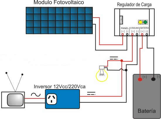
Laying of 2 lines can be interesting: one connected to batteries to feed points of low consumption lighting or LED and devices that consume DC and another connected to inverter to power appliances that consume AC.

The advantage of the inverter is that operating voltage is much higher and therefore the use of thick cables can be avoided. Especially when wiring is extremely long it may be economically feasible to use an inverter.

A feature that incorporates most modern converters is possibility of operating as battery chargers, taking alternating current from a generator or grid.

This is an extract of contents included in Technical-Commercial Photovoltaic Solar Energy Manual and Sopelia e-learning training.

All you need is Sun. All you need is Sopelia.

Solar Collectors Clamping And Anchoring

Proposed solution must comply, in order of importance:

– That it’s enough safe .
– That its cost be as low as possible.
– Speed and simplicity in assembly.

A method currently used is anchoring by chemical plug.

There are structures are of different materials. The most commonly used are aluminum and stainless steel.

Manufacturers usually sell the collector with its structure, although you can always design your own structure.

It is not advisable to transfer building cover with the anchor (it can cause leaks).

In case of large installations, a pre-assembly work can be carried out to make assembly on roof faster and cheaper.

In near coast areas, structure must be hot dip galvanized.

Screws should be made of stainless steel or corrosion resistant material.

Anchoring type will be based on:

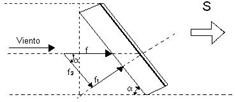
1) Wind forces that must endure. If collector is South oriented (we are in the Northern Hemisphere), wind that represents a risk is that coming from North (it is the inverse if we are in the Southern Hemisphere), which will exert tensile force on the anchors. The South wind will exert compressive force, not so dangerous. Wind force on a surface is:

f = P. S. sen2α
f = Weight to counteract wind strength.
P = wind load (Kg / m2).
S = collector surface (m2).
sin2α = angle of inclination sine.

Wind force is decomposed into f1, which incites perpendicularly to collector surface and in f2, which does it in parallel.

f1 force is at the end what counts and what is obtained from previous formula.

2) Collectors orientation and inclination. Collectors are oriented towards Ecuador. Normally, if we are in Southern hemisphere, they are oriented towards North and vice versa. Deviations of up to 20% with respect to optimal orientation do not significantly affect system performance and thermal energy contributed.

Collector’s inclination angle will depend on solar equipment use. Orientates inclinations:

• All year use (H.W.S.): inclination angle equal to geographical latitude.

• Winter preferably use (heating): inclination angle equal to geographical latitude + 10º.

• Summer period preferred use (outdoor pools heating): inclination angle equal to geographical latitude – 10º.

Variations of ± 10º with respect to optimum inclination angle practically do not affect performance and useful thermal energy provided by solar equipment.

3) Collecting surface must be free of shadows. In the most unfavorable day of use period, installation must not have more than 5% of useful surface area covered by shadows.

Projected shadows practice determination is made observing environment from collector´s lower edge midpoint, taking the North-South line as a reference.

By making an angular sweep on both sides, we will try to locate nearby obstacles with an angular height greater than 15º / 25º.

A more accurate determination of possible shadows can be made using system sizing software based on simulation methods.

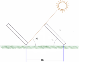
4) Minimum distance between collectors. Separation between collectors rows must be established so that at solar noon of most unfavorable day (minimum solar height) of use period, the shadow of upper edge of a row will be projected, at most, on lower edge of following row.

The formula of minimum distance between collectors is:

DT = L (senα / tan H + cosα)
H is the minimum solar height, which is:
H = (90º – latitude place) – 23.5º
L is collector´s height

If collector’s rows were arranged on a non-horizontal surface, expression would become:

DT = L ((sin (α – β) / tan (H + β) + cos (α – β))

α is still collector inclination angle respect to horizontal.

β is roof inclination angle respect to horizontal. It is positive if cover inclination angle direction coincides with that of collector; and with a negative value otherwise.

5) Finally, calculations must be carried out to ensure that cover or support will be able to support collectors weight, and that of the tank in case of thermosiphon and compact systems.

The R + D + I area of Sopelia has developed Solar Layout, the mobile app that allows collectors and modules to be optimally located at installation site.

All you need is Sun. All you need is Sopelia.

Solar Energy Mexico

Mexico became the sixth most attractive global economy for renewable energies in the last four years, following an energy reform enacted in December 2013 that attracted investments for US$ 8,600 million.

Prices that resulted from three long-term auctions carried out by the state regulator from 2014 to date, showed a downward trend and have been considered among the most competitive in the world.

With 70% of its sunny territory and an energy reform that opened doors to innovation and private investments, Mexico is on its way to becoming a future world leader in solar energy.

Resultado de imagen de energía solar mexico

A 2009 report by German Corporation for International Cooperation concluded that Mexico could generate all its electricity with a single solar mega plant in the Sonoran desert. Country would even have energy left over for export.

Mexico is the fourth largest producer of electricity from geothermal energy and has more than 230 plants in operation and construction for renewable energy electricity generation.

Country has raised the stakes with actions such as the second energy auction for 2019 and the recent energy reform to ensure that 35% of its energy comes from renewable sources in 2024.

The estimated investment within the next 15 years is US$ 119 billion, with which this sector will be the second with highest investment after automotive industry.

Oaxaca and Veracruz are the states with more wind and biomass projects respectively, while states such as Sonora, Chihuahua and Durango are the states with the most photovoltaic park installation projects.

In Sonora State, the construction of four new electricity generation plants based on solar energy is planned.

These projects will have a capacity of 498 MW and will invest U$D 423 million in next three years.

They will be added to the three solar plants that are already in operation, together with the solar-photovoltaic projects AT Solar I-V Blumex Power and Orejana.

The Tastiota and El Mayo solar plants will also be built, which will have 100 MW and 99 MW capacity respectively.

The Bacabachi I solar plant will have a capacity of 200 MW and April solar plant, 99 MW.

Resultado de imagen de energía solar mexico

However, in the country, it is necessary to carry out sophisticated engineering processes and route plans for optimal transport, since deficiencies in infrastructure are still observed.

In addition, upon arrival in Mexican territory, it is necessary to ensure that imported products comply with the necessary regulations, so assistance of true experts is required to verify the use of sectoral programs that allow cost savings, as is the case of steel (PROSEC), during components used in the solar parks importation.

All you need is Sun. All you need is Sopelia.

Free Solar Tools (IV)

On Internet we can find free tools for basic or low complexity solar systems dimensioning and for certain components or accessories estimation.

Sopelia research team has carried out an exhaustive search and testing from which a new corporate website section called Free Solar Tools has been created.

Selected tools were classified into 4 categories.

Today we will analyze the fourth of them: Solar Photovoltaic.

In the first category we have already analyzed tools to obtain data about solar resource and other variables to be considered in energy estimation solar system will provide in our location.

In the second category we have analyzed tools to calculate the “load”, ie the energy demand to be met.

In the third category we have analyzed tools for solar thermal systems dimensioning and system accessories estimating.

Now we are going to analyze tools for solar photovoltaic systems dimensioning and to estimate others individual components of a system.

The order of the tools is not random. We have prioritized the most intuitive, the most universal and those that can be used online without download.

For this fourth category our selection is as follows:

1) Solar Calculator

Approximate calculation tool from which budget, production data and system performance study is automatically obtained.

A Navigation Guide and Manuals can be found at page bottom.

Resultado de imagen de sistema solar fotovoltaico

2) Off-grid Solar Systems Calculator

Free online application for off-grid solar systems calculation.

It allows users to introduce new components from any manufacturer and product datasheets to be considered in the calculation.

Resultado de imagen de sistema solar aislado

3) Off-grid Systems Scale Calculator

Solar basic estimation of off-grid systems. Solar modules, batteries, controller and inverter calculation.

Resultado de imagen de sistema solar aislado

4) Solar Water Pumping Calculator

Calculator to obtain approximate energy needs figures for solar water pumping.

Resultado de imagen de bombeo solar de agua

5) Solar & Wind Energy Systems Calculation

Tool which determines requirements to meet solar and / or wind contribution for electrification and pumping needs.

Resultado de imagen de sistema eólico solar

6) Grid Connected System Online Simulation

Online application to estimate production and economic income of a grid-connected system.

Resultado de imagen de sistema solar conectado a red

7) Battery Bank Capacity Calculator

Calculator to estimate battery bank size needed to keep consumption by solar operation.

Resultado de imagen de banco de baterías solares

8) Wire Section Calculator

Tool in JavaScript format for copper and aluminum DC wire calculation.Resultado de imagen de cable solar

All you need is Sun. All you need is Sopelia.

The Solar Charge Controller

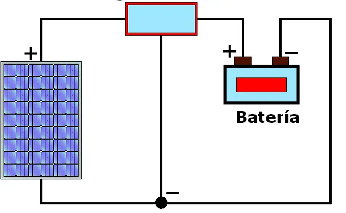
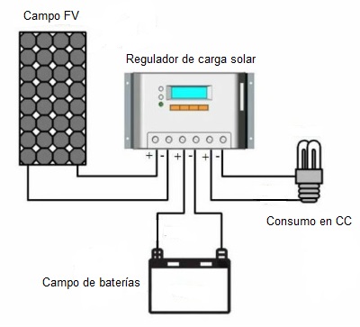
Charge controller is a device located between photovoltaic modules and batteries as an element of an isolated solar system.

Modules output voltage is set some volts higher than voltage battery needs to charge. The reason is to ensure that modules will always be able to charge the battery, even when cell temperature is high and generated voltage decreases.

This causes the drawback that once battery reaches its full charge state, module continues to try to inject energy producing an overload that, if not avoided, can destroy battery.

Charge controller is responsible for extending batteries life protecting them from overload situations, controlling load phases depending on their status and even reaching the cut depending on load needs of them.

Charge controllers may be working in one of the following situations:

Equalization status: equalization of batteries charge, after a period of low charge.

Deep charging state: regulation system allows charging until reaching final load voltage point.

Float state: battery has reached a charge level close to 90% of its capacity.

State of final charge and flotation: regulation system zone of action within Dynamic Flotation Band (range between final load voltage and nominal voltage + 10%).

To know which regulator to incorporate into a photovoltaic system it is necessary to know some elementary parameters.

First, one is isolated solar system nominal voltage. Batteries voltage and photovoltaic solar field define this voltage. Typical values are 12, 24, 48 and up to 60 volts.

The other parameter is photovoltaic modules system load current. It is recommended to multiply short circuit current Isc under standard conditions by 1.25 so that charge controller is always able to withstand current produced by modules.

Known system voltage and determined current value, we can choose the right charge controller. If there are still doubts, we can consult with provider technical department.

The simplest design is one that involves a single stage of control. Charge controller constantly monitors battery voltage but controls charge or discharge, never both. They are the cheapest and the simplest.

This can be achieved by opening the circuit between photovoltaic modules and battery (serial control) or by short-circuiting photovoltaic modules (shunt control).

Resultado de imagen de regulador de carga solar una etapa

In case of controllers that operate in two control stages, the two functions are controlled, both charge and discharge of battery. They are more expensive, but they are the most used.

Current charge controllers introduce microcontrollers and control 3 and up to 4 control stages.

Resultado de imagen de regulador de carga solar

During last years a new generation of charge controllers has been developed, whose main characteristics are to make photovoltaic field work at maximum working point and to always render it optimally.

These charge controllers are known as power maximizers or MPPT.

Another advantage of these devices compared to conventional controllers is the possibility of working with a different voltage in the generator field (solar panels) and batteries.

This directly influences in being able to put several modules in series, elevating system tension.

Working with lower currents we can reduce considerably voltage drop losses and use smaller cable sections and therefore of lower price.

For the choice of a conventional controller or an MPPT, we have to assess cost overruns that these systems have compared to benefits that it gives us due to system performance increase. In some cases, annual power increase can reach up to 30% compared to conventional controller.

Resultado de imagen de regulador de carga solar MPPT

Charge controller may not be essential in installations where the ratio between modules power and battery capacity is very small (eg: oversized batteries for safety reasons) so that charging current can hardly damage battery.

If modules field power in W is less than 1/100 battery capacity in W / h, charge controller may not be incorporated.

It can also be dispensed with a charge controller if system has self-regulated solar modules (not recommended for extreme climates).

This is an extract of contents included in Technical-Commercial Photovoltaic Solar Energy Manual and Sopelia e-learning training.

All you need is Sun. All you need is Sopelia.