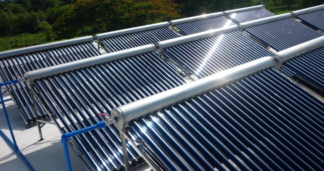
Thermal solar energy systems incorporate components that allow their correct operation and control. Some are mandatory (safety elements) and others are incorporated for better performance and maintenance of the system.
The expansion vessel is one of the essential safety elements for the system to work correctly, since its function is to absorb the expansion of the fluid at the moment it overheats.
Closed expansion vessels are the most widely used in solar thermal systems, since all of them are carried out in a closed circuit.
In this case, it is a hermetically sealed container divided into two chambers, one for fluid (1) and the other for gas (2), separated by a membrane (3) as can be seen in the diagram below.
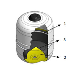
The membrane (high quality synthetic rubber) is flexible and allows chambers volume to be variable depending on each moment needs.
What is intended is to provide an extra capacity to the circuit, which allows it to absorb fluid expansion, so it must be dimensioned to support said expansion in the most unfavorable conditions.
When membrane has expanded to the maximum and the vessel can no longer absorb any more expansion, the circuit pressure will increase as the temperature of the fluid increases, until causing the safety valve to actuate (limit situation).
In principle, the expansion vessel can be located both at the outlet and at the return of the system because, as it is a closed circuit, the fluid expansion will be the same on one side as on the other. Despite this, it is always better to locate all components, if possible, in the cold part of the system for greater durability.
The expansion vessels will preferably be connected to the suction of the pump.
Another important component is the manometer. This element is used to know the pressure value in kg/cm2 inside a pipe or tank.

The choice of valves will be made according to the function they will perform and the extreme operating conditions (pressure and temperature).
The nominal pressure PN, expressed in bar or kp/cm2, and the nominal diameter DN, expressed in mm or inches, shall be stamped on the valve body, at least when the diameter is equal to or greater than 25 mm.
The minimum nominal pressure of all types of valves and accessories must be equal to or greater than 4 kp/cm2. The free diameters in the valve seats must correspond to their nominal diameters, and in no case less than 12 mm.
The characteristic valves of a solar thermal energy system are:
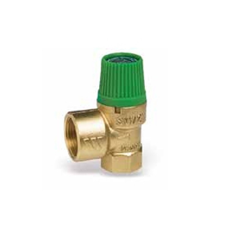
1) Safety valve: due to their important function, they must be capable of deriving the maximum power from the collector or group of collectors, even in the form of steam. Its placement is recommended in all circuits subjected to pressure and temperature variations.
The pressure at which the valve acts (set) allowing the fluid to escape must be less than the pressure that the most delicate element of the system can withstand, which is usually the expansion vessel or the manifold.
It is convenient to place a drainage funnel in the discharge to know when a safety valve acts.
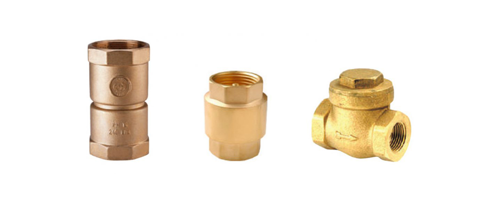
2) Non-return valves: they only allow fluid flow in one direction. Most used are:
– Those with a clapper: when the fluid circulates, it pushes a gate that closes immediately when circulation stops, preventing passage in the opposite direction. They produce little load loss, so they are recommended for primary circuits. It is not advisable to use them in diameters greater than 40 mm.
– The shell: when the fluid circulates, it pushes a spring, which moves the shutter shell, allowing its circulation. When circulation ceases, the howitzer returns to its initial position, preventing passage in the opposite direction.
They cause a greater pressure drop than those with clapet, so they are only recommended for secondary circuits subjected to mains pressure.
3) Stop valves: they are responsible for totally or partially interrupting the fluid flow through the pipes. Those of total closure separate a part of the installation or isolate it from the service. The partial closing ones produce an additional pressure drop in the circuit to regulate the flow or balance the system.
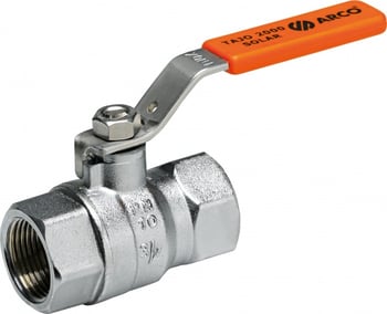
4) 3 and 4-way valves: they are used for fluid circulation through alternative routes. They are almost always placed with automatic devices so that an electrical signal, generally coming from a thermostat or probe, activates the mechanism by opening and closing corresponding pathways.
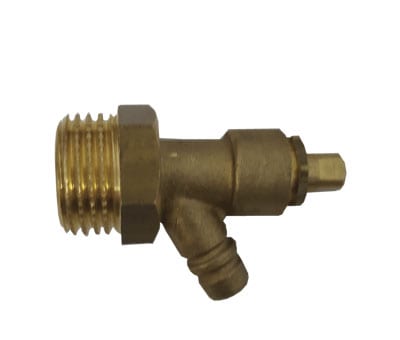
5) Drain valves: they are generally placed in the lower part of the circuits for maintenance operations or replacement of a damaged component of the system.
For different reasons (filling, cooling after a large expansion of the heat transfer fluid, etc.) solar thermal systems are sometimes affected by a problem that can impair their operation or greatly reduce their performance: air bubbles in inside the pipes.
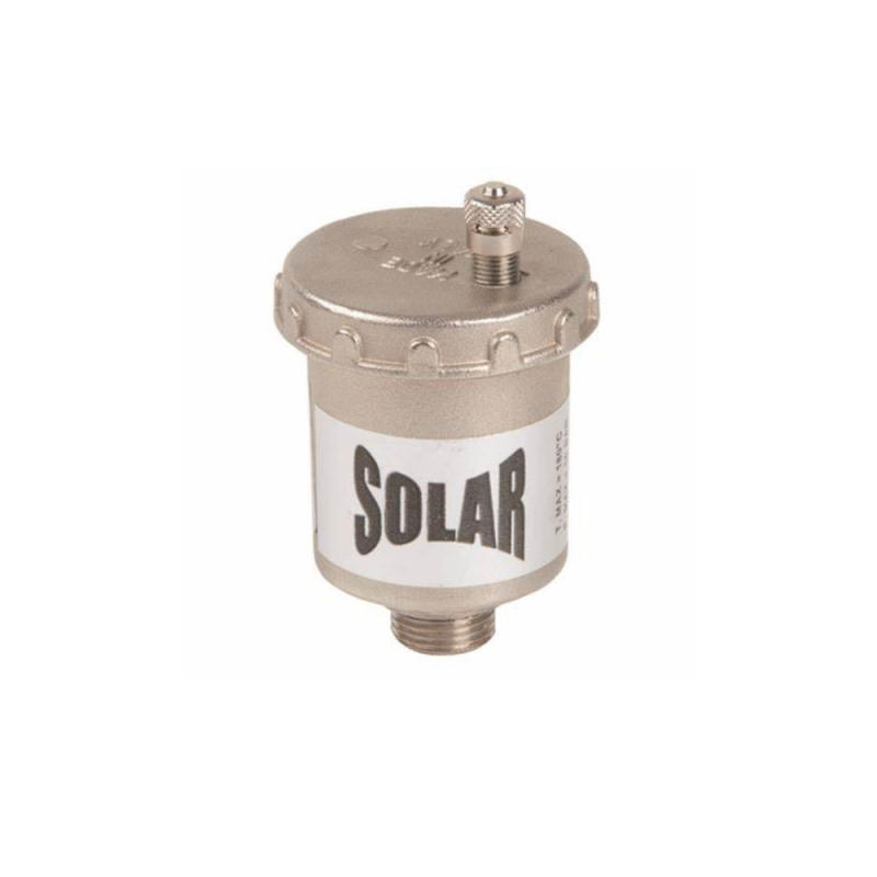
To eliminate bubbles from the heat transfer fluid, there are devices called purgers, which are designed to capture these bubbles and expel them to the outside.
Its operation is automatic, due to the fact that the bubbles tend to rise and settle above the fluid, the trap is placed at the highest point of the system.
Sometimes it is mounted on a deaerator, a device that has a great capacity to trap the bubbles in the fluid, the purger being in charge of evacuating the air.
The thermometer will allow us to measure the temperature of the fluid in different places of the system.
The most used are:
– Contact: they are placed by holding them on the pipes by means of a clamp.
– Immersion: they are inserted inside the pipe, accumulator or exchanger inside a sheath and are provided with a bulb of different lengths. Their reliability is greater because they are in direct contact with fluid.

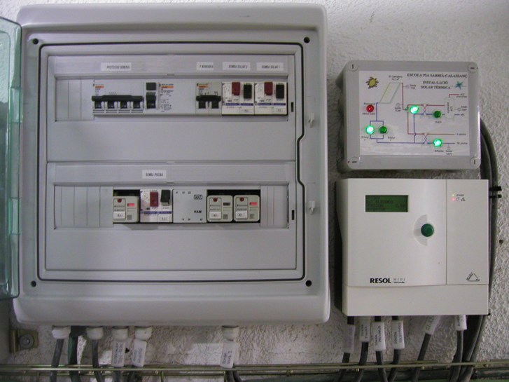
Thermostats are responsible for transforming a predetermined temperature reading on their scale into an electrical signal that activates a certain mechanism (starts or stops it) depending on the function entrusted to it.
The differential thermostat and the temperature probes that it has must ensure that the circulation pump only works when the collectors can provide a useful gain and stops when there is no capture or it is not sufficient.
One of the probes is placed at the outlet of the collectors and the other at the bottom of the storage tank. The differential thermostat will be connected to the circulation pump. Connections must be made with solder and wires must not have splices.
The mission of the differential thermostat is to compare the temperatures recorded by the probes, so that when there is a predetermined temperature difference between them favorable to the collectors, the circulation pump starts up.

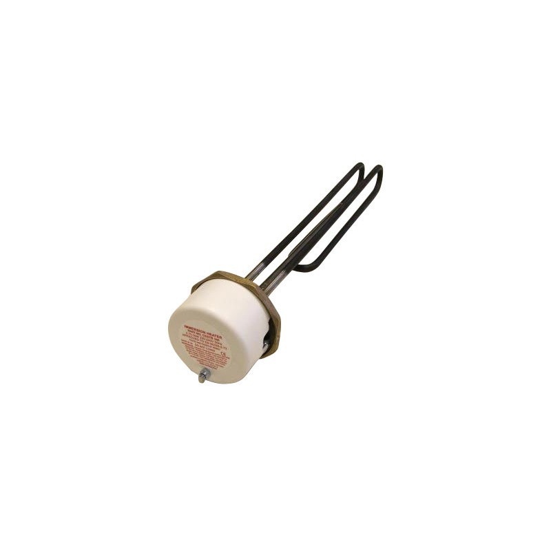
The immersion electrical resistance is an element widely used as an auxiliary system in solar energy systems for the production of DHW. As it is a submerged hot spot in the circuit, it tends to accumulate calcareous deposits. To avoid this, some manufacturers incorporate it in the primary circuit. This is a serious mistake because this energy source can be given priority to the detriment of the energy coming from the collectors.
Medium and large systems have an electrical and control device.
The analog variables that must be measured by the monitoring system will be at least 6, and among which the following 4 must be included:
Cold water inlet temperature.
Solar hot water supply temperature.
Temperature of hot water supply to consumption.
Consumption water flow.
With the recorded data, the results will be analyzed and the daily performance of the system will be evaluated. These data will be filed in a historical record of benefits.
This content was extracted from the Solar Thermal Energy Technical-Commercial Manual and is part of Solar e-learning.
All you need is Sun. All you need is Sopelia.

