Category Archives: Solar Photovoltaic Energy

ISOLATED PV SOLAR SYSTEMS DIMENSIONING

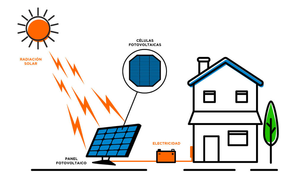
Isolated PV systems do not need a connection to an electrical network and their operation is independent or autonomous from said network.

Applications that are currently being implemented the most are small installations for lighting houses that are not reached by the general network, pumping, various agricultural facilities, signaling, hostels, campsites, shelters, summer and weekend chalets.

The criterion followed in isolated PV systems sizing is not so much to produce maximum energy but rather the concept of reliability appears (to ensure the proper functioning of the system, ensuring that failures are minimal).

Sizing an isolated photovoltaic system requires 7 steps:

1. Estimation of electrical load (electrical consumption)

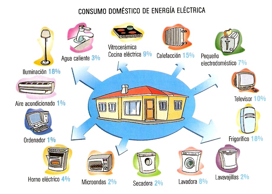
We must know power of each element of consumption and the estimated time of use. Normally the calculation is made using W / h as the unit of energy.

To estimate these values we can consult following link

Ver las imágenes de origen

2. Estimation of solar energy available

Hm is the energy in kWh that affects a square meter of horizontal surface on an average day of month m. From the corresponding table the value is obtained in MJ / m2 (mega joules / m2).

The conversion must be carried out and expressed in Wh / m2 or kWh / m2. Being 1 MJ at 277.77 Wh or 0.277 kWh.

To estimate these values we can consult following link

Ver las imágenes de origen

3. Battery sizing

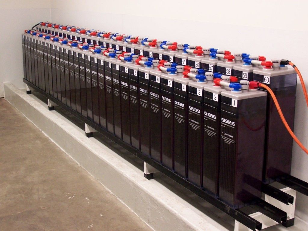
To define accumulator size, you must set N (Days of autonomy). It is the number of consecutive days that in the absence of Sun, accumulation system is able to meet consumption, without exceeding maximum discharge depth of the battery.

Having identified N and knowing the total energy required Et (final electricity consumption) in a period of 24 hours, we are going to calculate the real energy Er that the modules must contribute to the chosen battery (which will have a maximum admissible discharge depth pd).

The daily energy Er must take into account the different losses that exist:

Er = Et / R

Where R is a global factor of installation performance, whose value will be:

R = 1 – [(1-kb-kc-kv) ka. N / pd] – kb – kc – kv

kb: coefficient of battery performance. It varies between 0.05 (if there are no intense discharges) and 0.1 (for more unfavorable cases).
ka: self-discharge coefficient. If the data does not appear on the battery’s technical sheet, it can be estimated at 0.005 (0.5% daily).
kc: loss coefficient in the converter. If the system does not incorporate an inverter, it is zero. It ranges from 0.2 for sine wave inverters to 0.1 for square wave inverters.
kv: coefficient of other losses. It is usually estimated at 0.15 and 0.05 if we have already considered the performance of each device when calculating consumption.

Once R is calculated and Er obtained, we proceed to determine the useful capacity Cu of the battery. The battery must be able to accumulate the energy to be supplied throughout this period:

Cu = Er. N

To go from Wh to Ah, we will divide Cu by the nominal battery voltage (usually 12 V or 24 V).

Now we calculate the maximum nominal capacity C assigned by the battery manufacturer. These capacities will be assigned for temperatures between 20º and 25º C.

C = Cu / pd

With these data, the batteries offered on the market will be selected that most closely approximates the nominal capacity C obtained.

To estimate these values we can consult following link

Ver las imágenes de origen

4. Dimensioning of modules area

Energy originating in modules that must reach the accumulator (Er) suffers losses originated by the regulator, which are estimated at approximately 10%; therefore the daily amount of energy to be produced by the Ep modules is:

Ep = Er / 0.9

From the following formula we will calculate the HSP (hours of peak sun or hours of sun at an intensity of 1000 W / m2), starting from H expressed in MJ (1 kWh = 3.6 MJ):

HSP = 1 / 3.6k. H (MJ) = 0.2778 k. H

k is the correction factor for modules inclination according to the latitude of installation location.
H is the average daily radiation of each month expressed in MJ / m2.

To access these values we can consult following link

As we have already said, we must base ourselves on the most unfavorable month and also correct according to area climatological factors (clean atmosphere or mountain area = 1.05; area with pollution = 0.95; area with fog = 0, 92).

The ideal orientation is always towards equator and to determine the inclination we can follow recommendations in PV modules support structure post.

To calculate modules number we will use the following formula:

NM = Ep / 0.9. Pp. HSP

Pp is nominal (peak) power of chosen modules. The most suitable modules combination for the installation will be selected (price, available space, load to satisfy, etc.).

It is multiplied by 0.9 to consider possible additional losses that can cause modules dirt, reflection, etc.

If result is not a whole number, it will be rounded to the higher unit if decimal is equal to or greater than 0.5 and lower if it is less than 0.5.

Knowing the total modules number of PV generator and battery nominal voltage, which coincides with installation nominal voltage, it is possible to determine if it is necessary to group the modules in series and in parallel. The number of modules to be connected in series is calculated as follows:

Ns = VBat / Vm

Where:
Ns modules number in series per branch
VBat nominal battery voltage (V)
Vm nominal voltage of the modules (V)

And the number of branches in parallel to connect to supply the necessary power is given by:

Np = NM / Ns

Where Np is the number of modules to be connected in parallel branches.

Ver las imágenes de origen

5. Specify the controller or regulator

For sizing we can consult Solar charge controller post.

The installation will be dimensioned in such a way that the safety factor corresponds to a minimum of 10% between maximum power produced and that of regulator. The minimum possible number of regulators will be used.

To find the number of regulators Nr we will use the following equation:

Nr = Npp. ip / go

Being:
Npp the number of modules in parallel.
ip the peak intensity of the selected module.
go the maximum intensity that the regulator is capable of dissipating.

Ver las imágenes de origen

6. Sizing of the inverter

When sizing the inverter, the power demanded by the load made up of AC devices will be taken into account, so that an inverter will be chosen whose nominal power is slightly higher than the maximum demanded by the load.

For inverter sizing if PV systems has AC devices we can consult Solar converter post.

Ver las imágenes de origen

7. Choice of cable section

To select the cable section, the recommendations in the section Other elements (Wiring) post will be taken into account.

The sizing of the wiring constitutes one of the tasks in which special attention must be paid, since whenever there is consumption there will be losses due to voltage drops in the cables.

We can consult Solar wiring post.

Ver las imágenes de origen

This is an extract of contents included in Technical-Commercial Photovoltaic Solar Energy Manual and Sopelia e-learning training.

All you need is Sun. All you need is Sopelia.

On-Grid Systems Dimensioning

There are two modes of on-grid connection:

– User continues to buy the electricity they consume from distributor at the established price and also owns an electricity generating system that can bill the kWh produced at a higher price.

– In Self-consumption or “Net Metering” the system will be able to inject energy into the network when its production exceeds self-consumption, and extract energy from it otherwise.

A 1.5 kWp system occupies about 22 m2 of roof (12 m2 of modules net surface) and will feed as much energy to the grid as that consumed by a small house throughout the year.

COMO CONECTAR PANELES SOLARES A SU PROYECTO SOLAR

Estimation of energy produced by an on-grid PV system we will carry out is a simple prediction that consists of mere multiplication of an irradiation value by another of peak power that usually leads to estimates that are far from system real behavior.

An approach to more exact calculations should consider different factors that influence the useful energy generation process (PV generator location, temperature variations, shadows, maximum available power, second-order phenomena, inverter characteristics, etc.).

Whatever procedure adopted, we should try to combine simplicity with precision.

When calculating an on-grid PV system, following conditions must be taken into account:

1- System nominal power (kWp)

In practice, it will be established based on available surface area, investment to be made and amount of solar electricity to be generated.

Once module power to be used is determined, Wm, we multiply it by modules number to be installed Nm to obtain system peak nominal power Pmp:

Wm. Nm = Pmp

2- Electric energy to generate

The energy that could be obtained for each month can be calculated using the following expression:

Em = km. Hm. Pmp. PR. nm / GCEM

Where:

Em is solar energy production of month m in kWh.

km is correction factor to be applied due to modules inclination for month m (its values for northern hemisphere can be accessed in Censolar tables and at http://www.cleanergysolar.com/2011/09/15/tutorial-tables-correction-factor-of-k/) according to latitude of system location.

Hm is energy in kWh that affects a square meter of horizontal surface on an average day of month m. From the corresponding table the value in MJ / m2 (mega joules / m2) is obtained. The conversion must be carried out and expressed in kWh / m2.

To obtain the average daily radiation of each month expressed in MJ / m2 anywhere in the world, we can consult Opensolar DB.

The monthly mean daily irradiation can also be obtained from renowned databases such as NASA http://eosweb.larc.nasa.gov/sse or Joint Research Center [JRC], http://sunbird.jrc.it/pvgis /pv/imaps/imaps.htm Institute for Environment and Sustainable Renewable Energies, Ispra (Italy).

To convert from MJ to Wh or kWh we use the following equivalence:

1 MJ = 106 J = 0.277 kWh = 277.77 Wh

Pmp is the peak power of the generating field expressed in Kwp.

PR is the system energy performance factor or performance ratio defined as system efficiency in real working conditions. In practice, PR = 0.8 is usually taken

nm is number of days in month considered.

GCEM = 1kW / m2 CEM means Standard Measurement Conditions universally used to characterize solar generators, which as we have already seen are equivalent to: Solar irradiance: 1000 W / m2; Spectral distribution: AM 1.5 G; Cell temperature: 25 ° C.

Sistema solar fuera de la red o conectado? Diferencias, ventajas y desventajas

Estimate of the energy injected annually into network will be obtained by adding the energy values Em for each of the twelve months of the year.

The key element in a grid-connected system is the inverter, which ensures that the circuit-module-grid coupling is perfect, safe and efficient.

This content was extracted from the Commercial Technical Manual of Photovoltaic Solar Energy and is part of Sopelia Solar e-learning.

All you need is Sun. All you need is Sopelia.

PV Systems

Coupling of two or more modules in series produces a voltage equal to the sum of individual voltages of each module, keeping the intensity unchanged.

In parallel connection, it is the current that increases while voltage remains the same.

The most common is to select modules of desired voltage (those of 12 V are the most used) and combine them in parallel so that the total intensity (and therefore resulting power) is necessary to satisfy the electrical demand.

Interconnecting modules must have the same i-V curve to avoid decompensation.

If in a group of modules connected in series one of them fails (due to failure or shade), this module becomes a resistive load that will hinder or prevent the passage of the current generated by the other modules in the series. The module in question could be totally damaged.

To prevent this situation, modules connected in series are equipped with a by-pass or bypass diode, connected in parallel between their terminals. This element provides an alternative path to current generated by the other modules in the series.

There are different types of configurations that respond to systems characteristics and especially to load type. Most common ones are detailed below:

• Modules directly connected to a load
It is the simplest system. Photovoltaic generator connects directly to the load, normally a direct current motor. It is used for example in pumping water. In absence of batteries or electronic components, reliability increases but it is difficult to maintain efficient performance throughout the day.

Ver las imágenes de origen

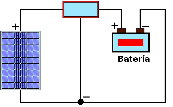
• Modules and battery
This setting can be used to replenish self-discharge of a battery or in small power rural electrification systems. One or two modules connected in parallel are usually used to achieve the desired power.

Ver las imágenes de origen

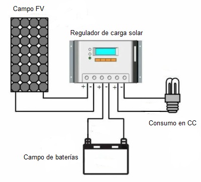
• Modules, battery and regulator
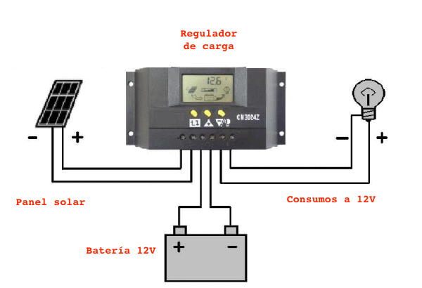
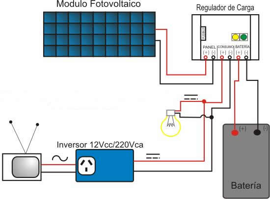
In this configuration, photovoltaic generator is connected to a battery through a regulator so that it is not overcharged or reaches an undesired depth of discharge. Batteries supply loads in direct current.

Ver las imágenes de origen

• Modules, battery, regulator and inverter
When AC power is required, an inverter will be incorporated into the scheme of previous configuration. Power generated in the photovoltaic system can be completely transformed into AC or DC and AC loads can be simultaneously supplied.

Ver las imágenes de origen

• Network connected systems
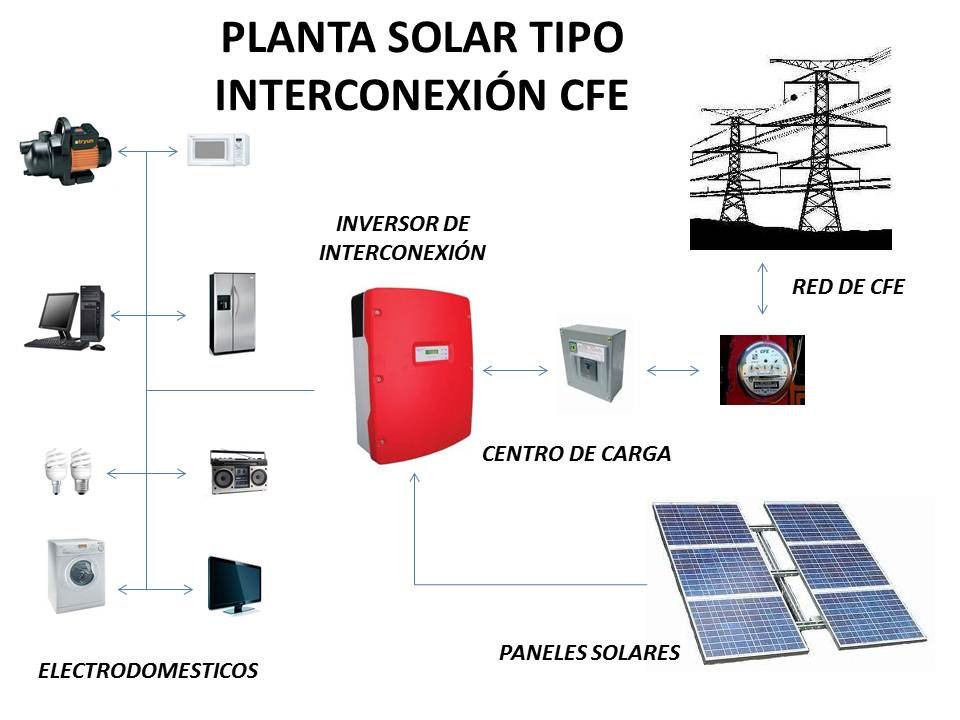
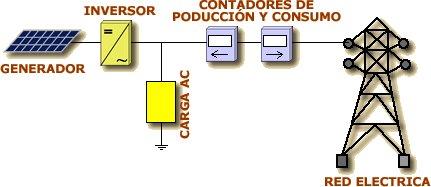
Grid-connected photovoltaic systems are made up of a photovoltaic generator that is connected to the conventional electrical grid through an inverter.

Ver las imágenes de origen

There may be two cases:

– The system injects energy into the network when its production exceeds self-consumption, and extracts energy from it otherwise.
– The system only injects energy into the network.

Fundamental difference between an isolated photovoltaic system and those connected to the grid consists in the absence, in the latter, of the battery and charge regulation.

The inverter, in grid-connected systems, must be in phase with the grid voltage.

Here are some examples of photovoltaic systems:
– Centrals connected to network with subsidy production.
– Microwave and radio repeater stations.
– Villages electrification in remote areas (rural electrification).
– Medical facilities in rural areas.
– Electric current for country houses.
– Emergency communication systems.
– Environmental data and water quality surveillance systems.
– Lighthouses, buoys and maritime navigation beacons.
– Pumping for irrigation systems, drinking water in rural areas and watering holes for livestock.
– Beaconing for aeronautical protection.
– Cathodic protection systems.
– Desalination systems.
– Recreational vehicles.
– Railway signaling.
– Systems for charging ship accumulators.
– Power for spaceships.
– SOS posts (road emergency telephones).
– Parking meters.
– Recharge of scooters and electric vehicles.

This content was extracted from the Commercial Technical Manual of Photovoltaic Solar Energy and is part of Sopelia Solar e-learning.

All you need is Sun. All you need is Sopelia.

Solar Tracking Systems

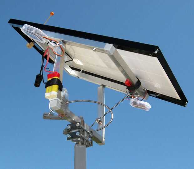
To harness as much solar energy as possible, collection surface must always be perpendicular to the sun’s rays and this can only be achieved if modules are equipped with a solar tracking mechanism.
Using these mechanisms, total energy received in a day can be up to 35% higher compared to that received by a static module.

This difference in performance is reduced in cases of frequent cloudy days and in all those weather conditions in which the relationship between energy received by direct radiation and that received by diffuse radiation tends to decrease. That is why it is only recommended to use it in areas of low cloudiness.

A detailed analysis must be carried out to verify that performance increase achieved more than compensates for energy consumption and the cost and maintenance of monitoring mechanisms.

The two types of movement are:

1. Single axis: only allows rotation around a horizontal, vertical or inclined axis. You can track sun azimuth or height, but not both at the same time.

Ver las imágenes de origen

2. 2-axis: in addition to the east-west rotation movement, a second rotary movement on a horizontal axis is also possible by varying the module angle with respect to the horizontal plane. They can be monopost (a single central support) or carrousel (several supports distributed along a circular surface).

Ver las imágenes de origen

We can find different solar tracking systems. The most common are:

1. Passive tracking systems: These devices do not use electricity or have a motor. There are two North American patents. The first (Robbins Engineering) is based on Freon gas pressure expansion and contraction contained in two cylinders located on each side of the structure. The second (Zomeworks) is a gravity system based on the variation of the weight of a fluid contained in a container that when evaporated passes to another.

2. Tracking by sensors: the sensor is the element that allows the detection and measurement of the lack of direction between the sun vector and the normal to capture surface. The sensor is usually made up of pairs of photosensitive elements mounted on the module and moving in solidarity with it.
The photosensors use direct solar radiation to detect sun position. Tracking impossibility when sun occultations occur and need to spend time recovering address when sun reappears are inherent characteristics of all systems of tracking based on photosensors.
Deviation detected by the photosensors transmits an actuation signal that controls motors operation to achieve module movement. Constant speed motors are often used that operate intermittently so that the addressing error is kept within a tolerance band.
Systems using photosensors are used for small and medium systems.
Between one day’s sunset and the next day’s sunrise, the module must be placed in the sunrise position because once the sun has risen, much time would be lost in the 180º turn necessary to regain direction. For this, a clock is used that generates the appropriate order.

3. Tracking by calculated coordinates: this system follows sun position by calculating its astronomical coordinates and does not require solar rays physical presence. This circumstance renders coordinate systems immune to cloudy days and other circumstances that can produce addressing errors in a photosensor, as happens for example with flashes.
The use of computer controlled systems has the additional advantage that certain changes can be made at software level only.
It can also include additional functions such as bringing the modules to a position of maximum security against inclement weather or the return at night.

Sopelia has developed Solar Layout, the Android App that allows to obtain the inclination, orientation and distance between rows of photovoltaic modules at the installation site.

This content was extracted from the Commercial Technical Manual of Photovoltaic Solar Energy and is part of Sopelia Solar e-learning.

All you need is Sun. All you need is Sopelia.

Architectural Solar Integration

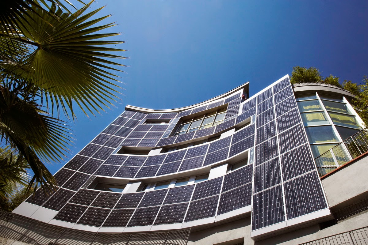
Photovoltaic solar energy is the one that best integrates into the urban environment. For this reason, architectural solutions that incorporate it have emerged. Some are listed below.

In homes with a tiled roof, these can easily be replaced by same type photovoltaic tiles, since it is not necessary to change canning or slats and roof structure remains the same.

Ver las imágenes de origen

Aluminum facades integrating photovoltaic cells are an alternative for new buildings or renovation projects.

Ver las imágenes de origen

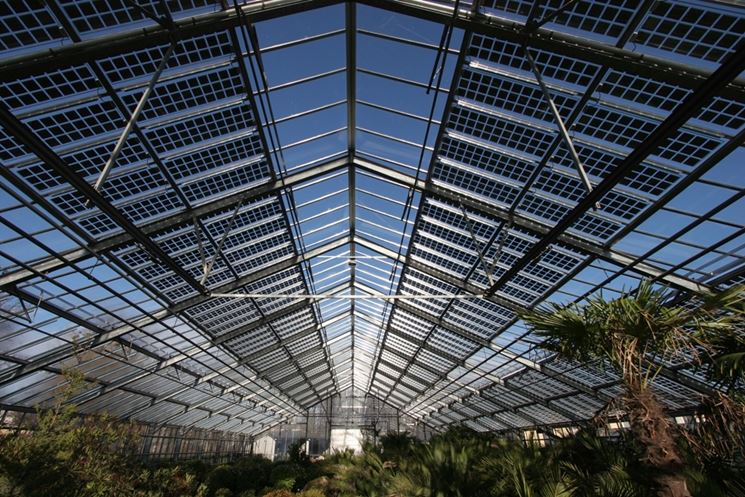
Photovoltaic modules with transparency together with aluminum profiles can be easily integrated into vertical walls, ceilings and roofs. These transparent modules are available in a wide range of applications, shapes and opacity.

Photovoltaic cells are embedded in the laminated safety glass. By varying glass weft position and density, it is possible to adjust light transmission and shadow effect inside the building.

For opaque solar modules in walls it is necessary to incorporate insulating materials that are behind to provide the necessary thermal barrier. The opaque and transparent modules can be combined on the same facade, improving building energy, thermal and acoustic efficiency.

Ver las imágenes de origen

In addition to producing clean electricity, ventilated photovoltaic facade system incorporates benefits in building thermal and acoustic insulation. The thermal envelope can cause savings of between 25-40% of the energy consumed in the building.

Ver las imágenes de origen

A photovoltaic skylight, in addition to photovoltaic generation, provides bioclimatic properties of thermal comfort inside the building due to the insulating glass air chamber. It also facilitates natural lighting and prevents UV rays and infrared radiation from penetrating into the building (improving comfort and avoiding premature materials aging).

Ver las imágenes de origen

A photovoltaic canopy constitutes a constructive solution that combines electrical energy generation with solar protection properties and against adverse weather conditions.

The orientation, the minimum slope, the dimensions or the wind and snow loads are important factors to take into account when designing the structure.

Ver las imágenes de origen

A photovoltaic car park consists of a structure that, in addition to protecting the vehicle, guarantees the in-situ energy generation for its grid discharge, self-consumption or electric car batteries supply.

Ver las imágenes de origen

The first photovoltaic ceramic floor has also been released. It consists of photovoltaic solar glass integrated in high ceramic pavements, these being fully passable. It can be integrated into any project and environment without this giving up the design or aesthetics of it.

Ver las imágenes de origen

Buildings, by integrating photovoltaic modules, create a world of possibilities. The great variety, shapes, colors and structures of photovoltaic cells, glass and profiles allow a modern architectural approach and also an innovative design combining elegance and functionality.

Sopelia has developed Solar Layout, the Android App that allows to obtain the inclination, orientation and distance between rows of photovoltaic modules at the installation site.

This content was extracted from the Commercial Technical Manual of Photovoltaic Solar Energy and is part of Sopelia Solar e-learning.

All you need is Sun. All you need is Sopelia.

PV Modules Support Structure

Regarding situation of photovoltaic modules, there are the following general possibilities:

Flooring: It is the most usual way of installing modules groups (especially in solar farms) and has great advantages in terms of wind resistance, accessibility and ease assembly.
However, it is more susceptible to being buried by snow, flooding or being broken by animals or people.

Ver las imágenes de origen

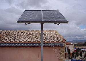
Pole: very used in small dimension systems, if it has a mast. It is the typical assembly type of isolated communication equipment or lampposts feeding.

Ver las imágenes de origen

Wall: good anchor points must be available on a built building. Accessibility can present some problems.

Ver las imágenes de origen

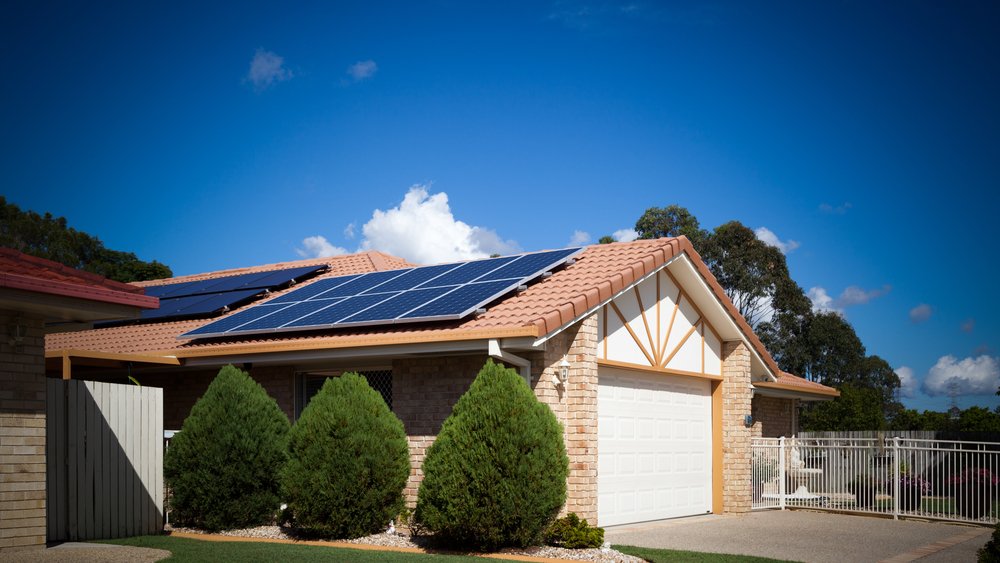
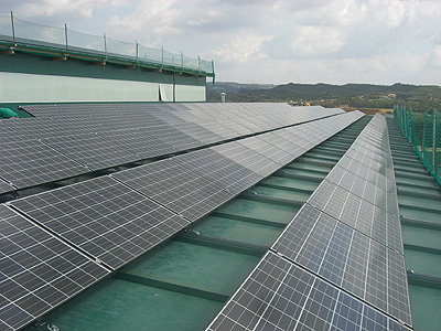
Roof: one of the most common because generally enough space is available. It also presents problems of snow cover and risks in roof fasteners waterproofing.

Ver las imágenes de origen

If system is located in an urban area, most common is to place the module on the roof.

In structure assembly, roof sealing must be ensured by waterproofing elements use.

A study must also be carried out to determine if ceiling will support modules and support structure weight.

However, main factor when fixing the structure is wind strength. Structure must withstand winds of at least 150 km / h.

On terraces or floors, the structure should allow a minimum height of the module of about 30 cm. In mountain areas or where there is abundant snowfall, it must be higher.

The structure and supports should preferably be anodized aluminum, stainless steel or galvanized iron and stainless steel fasteners.

Anodized aluminum is lightweight and highly resistant.

Stainless steel is suitable for very corrosive environments and has a longer useful life but its cost is high.

Galvanized iron structures offer good protection against external corrosive agents with the advantage that zinc is chemically compatible with lime and cement mortar, once these are dry.

Structures come in kits or standard profiles that are on the market and a specific system structure can be built.

Supports designed for a specific solar module are usually cheaper than those manufactured in order to be able to hold any type of module. However, it will surely be the latter that will end up developing in greater numbers in near future.

Normally, a solar modules support has the following characteristics: it has a plate provided on its upper face with quick coupling means for modules and one or more holes for the screws to be introduced and thus join the plate to the support. The support also has fastening means attached to plate lower face for fastening to lower structure.

Orientation will always be towards the equator and the following inclinations are recommended:

Systems with priority function in winter (eg: mountain lodge): 20º higher than place latitude.

Systems with uniform operation throughout the year (p.e .: home electrification): 15º greater than place latitude.

Systems with priority operation in spring and summer (p.e .: campings): same as place latitude.

Systems whose objective is to produce the greatest amount of energy throughout the year (eg: connection to the grid): 85% of place latitude.

The reason for inclination increasing, compared to that recommended for solar thermal collectors, is that generally in the case of photovoltaic systems there is no auxiliary energy system and it is necessary to capture all the energy possible in the most unfavorable period (winter).

Sopelia has developed Solar Layout, the Android App that allows you to obtain the inclination, orientation and distance between rows of photovoltaic modules at the installation site.

This content was extracted from the Solar Photovoltaic Energy Technical-Commercial Manual and is part of Solar e-learning.

All you need is Sun. All you need is Sopelia.

Solar Wiring

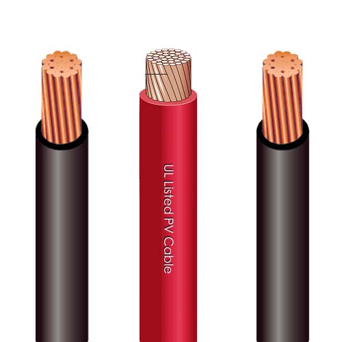
Cables, both direct current (DC) and alternating current (AC), if correctly sized, will minimize energy losses and protect the installation.

For a photovoltaic system, DC cables must meet some requirements:

* Have grounding line and protection against short circuit.
* Be resistant to UV rays and adverse weather conditions with a wide range of temperatures (approximately between -40ºC and 110ºC).
* Possess a wide voltage range (more than 2000 V).
* Be simple and easy to manipulate.
* Be non-flammable, of low toxic level in case of fire and without halogens.
* Have a very low conduction loss (up to 1%).

Photovoltaic installation cables must have certain characteristics that differentiate them from conventional cables, although many argue that differences are not very large.

Since voltage in a photovoltaic system is low DC voltage, 12 or 24 V, currents that will flow through the cables are much higher than those in systems with 110 or 220 V AC voltage.

Power amount in Watts produced by the battery or photovoltaic panel is given by the following formula: P = V. I

V = voltage in Volts
I = current in Amperes

This means that to supply a power at 12 V current will be almost 20 times higher than in a 220 V system. It implies that much thicker cables must be attached to prevent overheating or even a fire.

Following table indicates recommended cable section according to power and for different voltage levels.

For very low voltages and low power demands, very thick cables must be used. For example, to reach a power of approximately 1 Kw at 12 V we would need a 25 mm2 section cable. The same as to supply 20 Kw at 220 V.

This increases system price drastically because thicker cables are more expensive.

That is why it is very important that the lengths of DC wiring are as short as possible.

When designing large systems, a cost / performance analysis must be performed to choose most suitable operating voltage. It would be advisable to gather small groups of modules and if possible to make operating voltage higher than 12 or 24 V.

To verify cable section values recommended in tables, maximum voltage drops compared to voltage at which you are working should be below the 3% / 5% limit.

To calculate the relationship between conductor section and its length we can apply following formula:

S = 2 r. l. i / ΔV

Being:

r Conductive material resistivity (0.018 in case of copper conductors)
l Cable section length
i Current intensity
ΔV Voltmeter reading difference

Let’s see an example:

Battery terminals output voltage is 13.1 V. The main line between it and a device, which consumes 60 W, measures 12 m of 6 mm2 cable.

We must find the voltage value at device input to verify that we are within maximum recommended values of voltage drop.

The intensity i = P / V = 60 / 13.1 = 4.6 A

S = 6 = 2. 0.018. 12 4.6 / ΔV

ΔV = 0.33 V

Therefore, voltage at device input will be: 13.1 – 0.33 = 12.8 V

Voltage drop is 2.34% (maximum recommended value: 3%).

It is normal to use tables to select recommended section and use the formula to calculate the voltage drop and perform the verification.

In case that voltage recommended maximum values drop are exceeded, we will select section immediately above and we will carry out verification again.

Cables for photovoltaic applications have a designation, according to regulations, which is composed of a set of letters and numbers, each with a meaning.

Cables designation refers to a series of characteristics (construction materials, nominal voltages, etc.) that facilitate the selection of the most suitable to the need or application.

This is an extract of contents included in Technical-Commercial Photovoltaic Solar Energy Manual and Sopelia e-learning training.

All you need is Sun. All you need is Sopelia.

The Solar Converter

They are equipment capable of altering voltage and characteristics of electric current they receive to transform it into suitable for specific uses.

Those that receive direct current and transform it into direct current with a different voltage are called DC-DC converters. They are not widely used in photovoltaic systems.

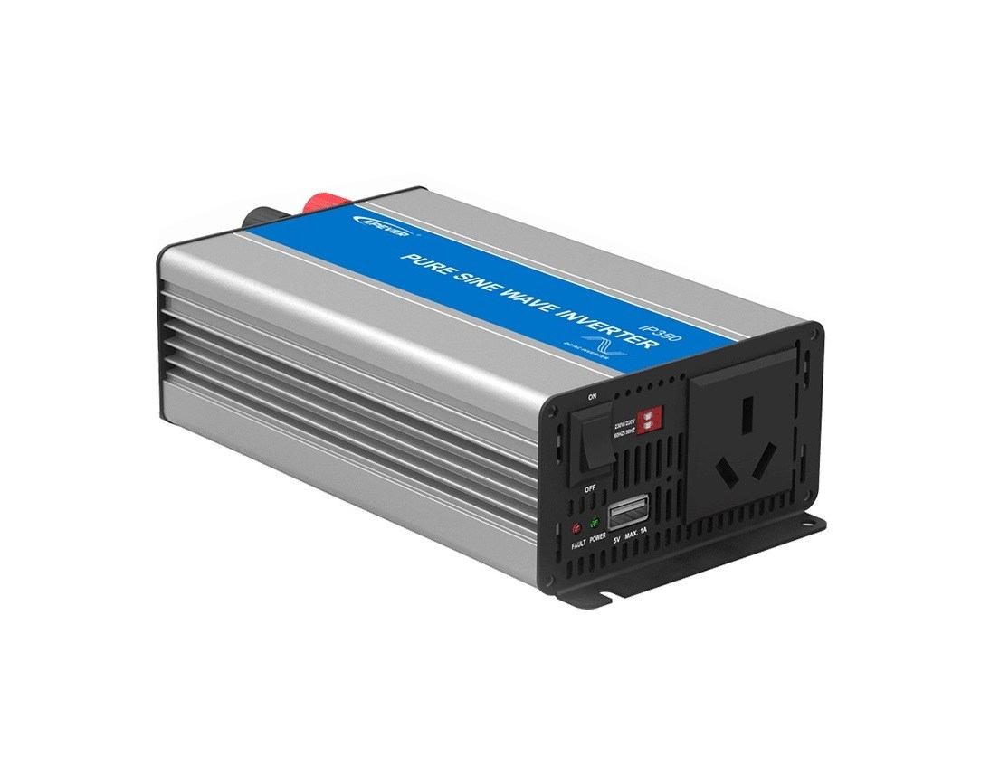
Those that receive direct current and transform it into alternating current are called DC-AC converters or inverters. The function of an inverter is to change a DC input voltage to a symmetrical AC output voltage, with the magnitude and frequency desired by user.

They allow to transform 12V or 24V direct current that modules produce and store batteries, in 125V or 220V alternating current.

This allows use of electrical devices designed to work with AC.

A simple inverter consists of an oscillator that controls a transistor, which is used to interrupt incoming current and generate a square wave. This square wave feeds a transformer that softens its shape, making it look like a more sinusoidal wave and producing the necessary output voltaje.

Ver las imágenes de origen

The voltage output waveforms of an ideal inverter should be sinusoidal.

This gives rise to different types of inverters:

1) Square wave inverters: they are cheaper, but less efficient. They produce too many harmonics that generate interference (noise). They are not suitable for induction motors.

Recommended if you want AC power only for a TV, a computer or a small electrical device. Inverter power will depend on device nominal power (for a 19 ” TV a 200 W inverter is enough).

Ver las imágenes de origen

2) Modified sine wave inverters: they are more sophisticated and expensive. They use pulse width modulation techniques.

Wave width is modified to bring it as close as possible to a sine wave. Harmonics content is less than in square wave.

They are the ones that offer best quality / price ratio for lighting, television or frequency inverters connection.

Ver las imágenes de origen

3) Pure sine wave inverters: with a more elaborate electronics, a pure sine wave can be achieved.

Until recently these investors were large, expensive and inefficient; but lately, has been developed equipment with 90% or more efficiency, telecontrol, energy consumption measurement and battery selection.

Ver las imágenes de origen

Since only induction motors and most sophisticated devices or loads require a pure sine wave form, it is usually preferable to use modified sine wave inverters; which are cheaper.

Inverters must be dimensioned from two variables.

First is considering electrical power wattages that inverter can continuously supply during its normal operation.

Inverters are less efficient when used at a low percentage of their capacity. For this reason it is not advisable to oversize them and they must be chosen with a power as close as possible to that of load consumption.

Second is starting power. Some inverters can supply more than their nominal capacity for short time periods. This capacity is important when using motors or other loads that require 2 to 7 times more power to start than to stay running once they have started (induction motors, high power lamps).

Incorporating an inverter is not always the best option from energy efficiency point of view. It may seem an easy solution to convert all solar system output to a standard AC power but it has several disadvantages.

First is that it increases system cost and complexity.

An inverter also consumes energy (in addition to 15% for performance loss) and therefore decreases overall system efficiency.

For a small house electrification (light points, TV and a small appliance) it is possible and profitable to do without the inverter.

For lighting it is better to invest in low voltage lights instead of investing in an inverter.

Laying of 2 lines can be interesting: one connected to batteries to feed points of low consumption lighting or LED and devices that consume DC and another connected to inverter to power appliances that consume AC.

The advantage of the inverter is that operating voltage is much higher and therefore the use of thick cables can be avoided. Especially when wiring is extremely long it may be economically feasible to use an inverter.

A feature that incorporates most modern converters is possibility of operating as battery chargers, taking alternating current from a generator or grid.

This is an extract of contents included in Technical-Commercial Photovoltaic Solar Energy Manual and Sopelia e-learning training.

All you need is Sun. All you need is Sopelia.

Free Solar Tools (IV)

On Internet we can find free tools for basic or low complexity solar systems dimensioning and for certain components or accessories estimation.

Sopelia research team has carried out an exhaustive search and testing from which a new corporate website section called Free Solar Tools has been created.

Selected tools were classified into 4 categories.

Today we will analyze the fourth of them: Solar Photovoltaic.

In the first category we have already analyzed tools to obtain data about solar resource and other variables to be considered in energy estimation solar system will provide in our location.

In the second category we have analyzed tools to calculate the “load”, ie the energy demand to be met.

In the third category we have analyzed tools for solar thermal systems dimensioning and system accessories estimating.

Now we are going to analyze tools for solar photovoltaic systems dimensioning and to estimate others individual components of a system.

The order of the tools is not random. We have prioritized the most intuitive, the most universal and those that can be used online without download.

For this fourth category our selection is as follows:

1) Solar Calculator

Approximate calculation tool from which budget, production data and system performance study is automatically obtained.

A Navigation Guide and Manuals can be found at page bottom.

Resultado de imagen de sistema solar fotovoltaico

2) Off-grid Solar Systems Calculator

Free online application for off-grid solar systems calculation.

It allows users to introduce new components from any manufacturer and product datasheets to be considered in the calculation.

Resultado de imagen de sistema solar aislado

3) Off-grid Systems Scale Calculator

Solar basic estimation of off-grid systems. Solar modules, batteries, controller and inverter calculation.

Resultado de imagen de sistema solar aislado

4) Solar Water Pumping Calculator

Calculator to obtain approximate energy needs figures for solar water pumping.

Resultado de imagen de bombeo solar de agua

5) Solar & Wind Energy Systems Calculation

Tool which determines requirements to meet solar and / or wind contribution for electrification and pumping needs.

Resultado de imagen de sistema eólico solar

6) Grid Connected System Online Simulation

Online application to estimate production and economic income of a grid-connected system.

Resultado de imagen de sistema solar conectado a red

7) Battery Bank Capacity Calculator

Calculator to estimate battery bank size needed to keep consumption by solar operation.

Resultado de imagen de banco de baterías solares

8) Wire Section Calculator

Tool in JavaScript format for copper and aluminum DC wire calculation.Resultado de imagen de cable solar

All you need is Sun. All you need is Sopelia.

The Solar Charge Controller

Charge controller is a device located between photovoltaic modules and batteries as an element of an isolated solar system.

Modules output voltage is set some volts higher than voltage battery needs to charge. The reason is to ensure that modules will always be able to charge the battery, even when cell temperature is high and generated voltage decreases.

This causes the drawback that once battery reaches its full charge state, module continues to try to inject energy producing an overload that, if not avoided, can destroy battery.

Charge controller is responsible for extending batteries life protecting them from overload situations, controlling load phases depending on their status and even reaching the cut depending on load needs of them.

Charge controllers may be working in one of the following situations:

Equalization status: equalization of batteries charge, after a period of low charge.

Deep charging state: regulation system allows charging until reaching final load voltage point.

Float state: battery has reached a charge level close to 90% of its capacity.

State of final charge and flotation: regulation system zone of action within Dynamic Flotation Band (range between final load voltage and nominal voltage + 10%).

To know which regulator to incorporate into a photovoltaic system it is necessary to know some elementary parameters.

First, one is isolated solar system nominal voltage. Batteries voltage and photovoltaic solar field define this voltage. Typical values are 12, 24, 48 and up to 60 volts.

The other parameter is photovoltaic modules system load current. It is recommended to multiply short circuit current Isc under standard conditions by 1.25 so that charge controller is always able to withstand current produced by modules.

Known system voltage and determined current value, we can choose the right charge controller. If there are still doubts, we can consult with provider technical department.

The simplest design is one that involves a single stage of control. Charge controller constantly monitors battery voltage but controls charge or discharge, never both. They are the cheapest and the simplest.

This can be achieved by opening the circuit between photovoltaic modules and battery (serial control) or by short-circuiting photovoltaic modules (shunt control).

Resultado de imagen de regulador de carga solar una etapa

In case of controllers that operate in two control stages, the two functions are controlled, both charge and discharge of battery. They are more expensive, but they are the most used.

Current charge controllers introduce microcontrollers and control 3 and up to 4 control stages.

Resultado de imagen de regulador de carga solar

During last years a new generation of charge controllers has been developed, whose main characteristics are to make photovoltaic field work at maximum working point and to always render it optimally.

These charge controllers are known as power maximizers or MPPT.

Another advantage of these devices compared to conventional controllers is the possibility of working with a different voltage in the generator field (solar panels) and batteries.

This directly influences in being able to put several modules in series, elevating system tension.

Working with lower currents we can reduce considerably voltage drop losses and use smaller cable sections and therefore of lower price.

For the choice of a conventional controller or an MPPT, we have to assess cost overruns that these systems have compared to benefits that it gives us due to system performance increase. In some cases, annual power increase can reach up to 30% compared to conventional controller.

Resultado de imagen de regulador de carga solar MPPT

Charge controller may not be essential in installations where the ratio between modules power and battery capacity is very small (eg: oversized batteries for safety reasons) so that charging current can hardly damage battery.

If modules field power in W is less than 1/100 battery capacity in W / h, charge controller may not be incorporated.

It can also be dispensed with a charge controller if system has self-regulated solar modules (not recommended for extreme climates).

This is an extract of contents included in Technical-Commercial Photovoltaic Solar Energy Manual and Sopelia e-learning training.

All you need is Sun. All you need is Sopelia.